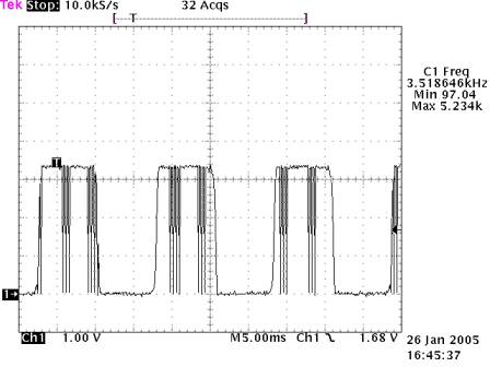
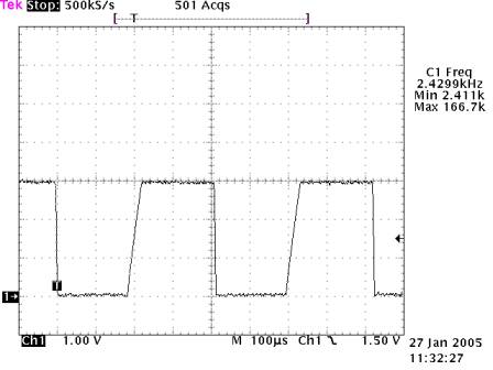
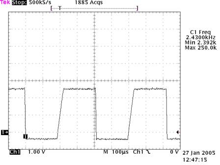
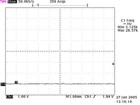
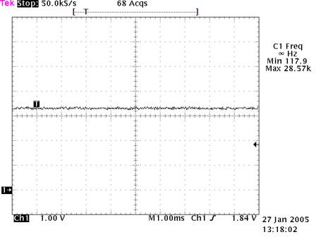
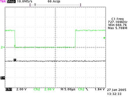
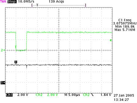
FigA, TP1, left: framerate 5 f/s, right: framerate 60 f/s
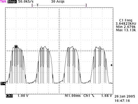
FigB, at TP2, both: framerate 5 f/s, left: mic-slider low, right: mic-slider high
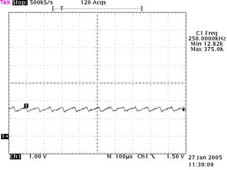
FigC, at TP2, both: framerate 60 f/s, left: mic-slider low, right: mic-slider high
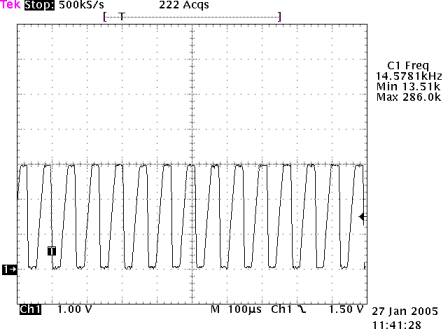
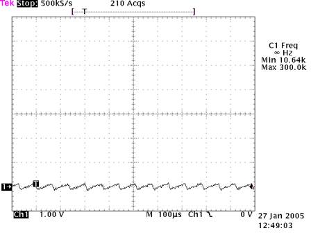
FigD, at TP3, both: framerate 5 f/s, left: mic-slider low, right: mic-slider high
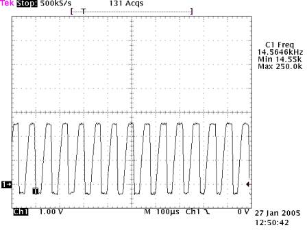
FigE, at TP3, both: framerate 60 f/s, left: mic-slider low, right: mic-slider high
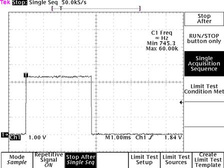
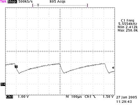
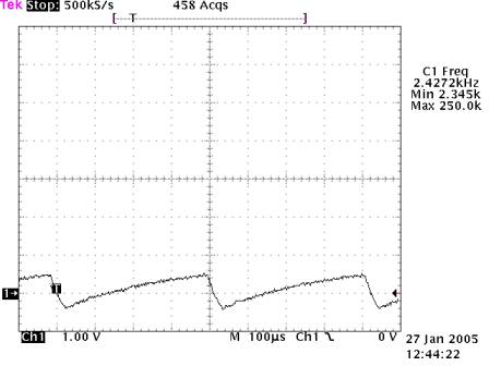
FigF, at TP4, manually triggered to proof pulse-width is higher than input clock period
FigG, at TP4, both: framerate above 25 f/s, left: mic-slider low, right: mic-slider high
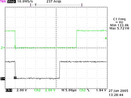
FigH, CH1=TP5,
CH2=TP6,
both: mic-slider high, left: framerate 5 f/s, right: framerate 60 f/s
charge transfer pulses are generated and differ slightly in lenght to the original
pulses
The left picture of FigH
proofs that this mod sometimes is working even with framerates below 25 f/s, but
I wouldn't take it
for granted. During development I discovered that sometimes the left signal of FigD is
enough to trigger the first multivibrator.
The additional 100k resistor (to guarantee operation at lower frame rates)
decreases the input resistance of the first
multivibator, thus decreasing the signal amplitude.
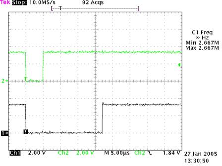
FigI, CH1=TP5,
CH2=TP6,
both: mic-slider low, left: framerate 5 f/s, right: framerate 60 f/s
charge transfer pulses are not generated, output of 2nd multivibrator stays high
Copyright © 2005
Michael Posavec
last update 04. feb. 2005
email: lateralusmail --> yahoo.de