USB only long exposure
modification for Philips ToUcam Pro
more astro hardware:
http://www.albireo.at/astrohardware/
The modification
I've made is based on Steve Chambers
SC1 modification and the further improvement by Phil
Davis, but does not use the additional parallel port connection.
I consider all differences from the original SC1 modification and Phil's
improvement as my intellectual property. Information from this homepage can be
used only for noncommercial purposes. I strictly forbid to sell this
information or webcams modified according to this instructions.
I do not guarantee that this modification will work with your Philips ToUcam Pro 840k, nor do I take over any responsibilites if your webcam, PC or any other related equipment is not working anymore after you've carried out this modification.
The original SC1 modification uses an additional parallel port connection to the PC to remote control the exposure time of the Philips ToUcam Pro 840k. You have to attach the webcam to the USB-port and the additional cable to the LPT-port of your PC. I figured out a way how you can remote control the exposure time with the USB cable only. You don't need this parallel port cable anymore.
(Fig.1 differences SC1-mod and USB-only mod)
As mentioned above, this modification does the same thing like the well known SC1 modification: it blocks the charge transfer pulses from the Philips SAA8116HL to the NEC PD16510 driver and disables the shutter.
Content
Schematic
Explanation
Modification
Conclusion
Pro's and Con's
There are only a few components you need:
| S1 | toggle switch |
| C1,C2,C3 | 100nF |
| R1,R2 | 100k |
| R3 | 330 |
| IC1 | 74HC423 (dual retriggerable monostable multivibrator with reset) |
DO NOT use a 74HCT423 for IC1, since it has different input voltage levels!
(Fig.2 schematic)
The circuit for disabling the shutter pulses looks slightly different than the one from the original SC1 mod. The reason why I've done this change is not very exiting: I had no change-over-switch in my lab, only an ON-OFF switch. So I tied pin 10 of PD16510 permanently to high (3,3V) via R1 and the output pin 97 of SAA8116HL can drive it low if S1 is closed. The benefit is a two wire connection to the switch instead of 3 wires.
Blocking the charge
transfer pulses was much more difficult:
The Philips processor SAA8116HL has an undocumented feature. As you can see in
the screenshot of the datasheet (Fig. 3) the processor has a "mode
decoder" with two inputs (named RESERVED2 and RESERVED3)
and one output (RESERVED1). I couldn't figure out what these inputs are good
for, but I discovered that RESERVED1
is the output of the PGA (programmable gain amplifier).
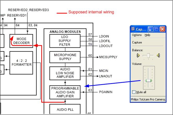
(Fig.3 supposed internal wiring of the RESERVED1 pin from SAA8116HL)
The webcam has a built in microphone which enumerates as standard USB-microphone
to the USB-host with PGA capabilities. By moving the volume slider of the
microphone on the PC, you can remote control the gain of the PGA. The
PROGRAMMABLE AUDIO GAIN AMPLIFIER unit in Fig.3 receives this volume slider
information and sets it's internal gain accordingly.
As you can see in Fig.2, I've changed the input to pin 61 of the SAA8116HL from the built in microphone to another signal. I use this signal as constant input to the AUDIO LOW NOISE AMPLIFIER and can control the amplification of this signal via the volume slider. Thus I get nearly no signal at pin 64 when the slider is at the minimum position and a square-wave signal when the slider is at the maximum position. This signal at pin 64 is used as clock for the first monostable multivibrator, which produces a permanent LOW signal on its output when the slider is at it's minimum position and a permanent HIGH signal when the slider is at the maximum position. This output signal of the 1st multivibrator is used as reset input for the 2nd multivibrator, which creates the transfer pulses or simply does nothing depending on the volume slider position. Both monostable multivibrators are located in one IC-package.
I decided to use the
74HC423 in an SO16 package, because I wanted to get a minimum sized modification.
You can use a DIP16 package if you don't have sufficient soldering skills.
However, you would have to find a different space for placing the DIP16 since it
is twice as big as the SO16.
Please refer to other homepages for instructions how to disassemble the webcam.
Fig.4 shows the schematic with the topside package-view of the used 74HC423.
(Fig.4 schematic with package-view)
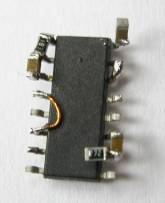
First you have to solder all resistors and capacitors to IC1 74HC423. The picture shows the bottom side of IC1. Make sure that the resistor and the capacitor (R2 and C2) have a connection to pin 15.
(ignore the values printed on the resistors of Fig.5, they are from an early development stage and do not represent final values)

(Fig.5 soldering of resistors and capacitors, click to enlarge)
Please scroll down to the bottom of this page (or use this link) to get more information about an additional resistor than can be placed during this step.
Step2:
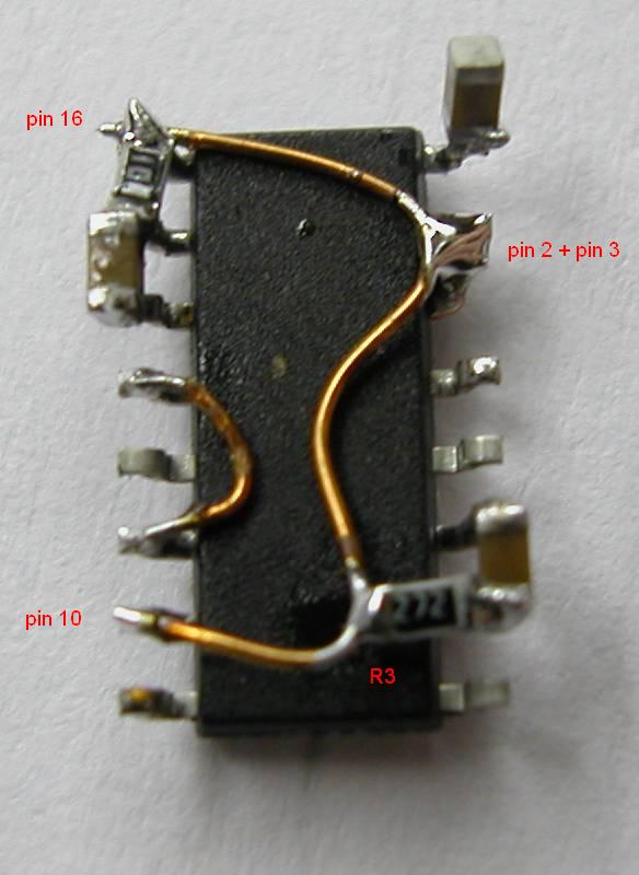
Bend pin 2 and pin 3 towards each other and solder them together. Take a short piece of wire, and solder pin 11 and 13 together. Take a longer piece of wire and connect together pin 16, the pin 2+3 pair, R3 and pin 10.
I've used copper magnet wires for all my wiring. That's a thin copper wire which is coated with a thin insulating film. You have to burn away this insulating film with your soldering iron if you want to connect this wire to a soldering point. This can be done by simply holding the soldering iron against the wire for some seconds (5-20 seconds, depending on the heat of your soldering iron).
(Fig.6 wiring on IC1, click to enlarge)
Step3:
Cut the original tracks on two positions. Don't make those cuts to deep, because the webcam has a multilayer PCB. You could easily cut tracks from layers underneath the surface-layer.
(Fig.7 original tracks are cut, click to enlarge)
Step4:
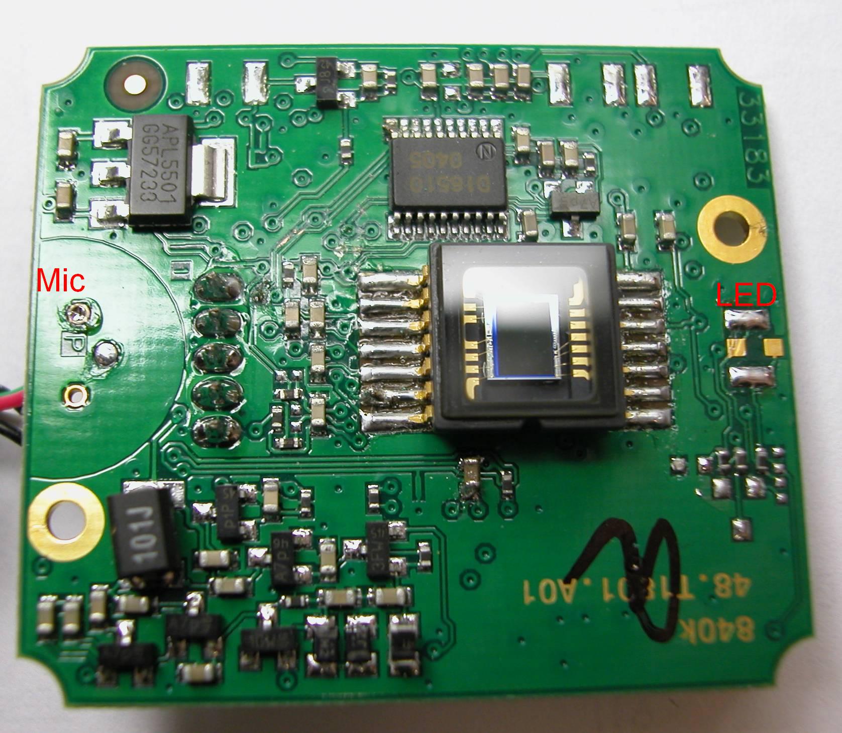
Remove the microphone and LED.
(Fig.8 microphone and LED, click to enlarge)
Step5:
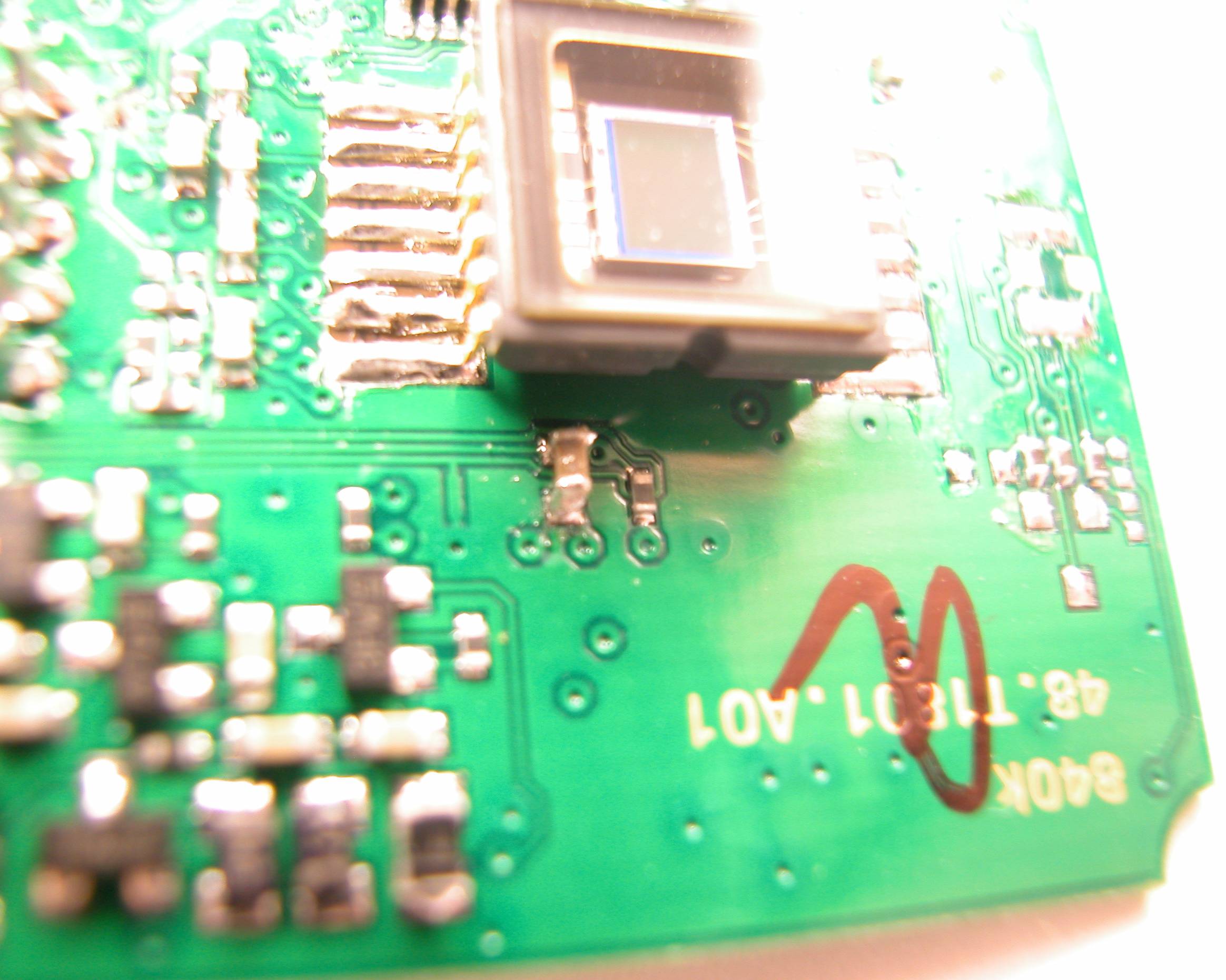
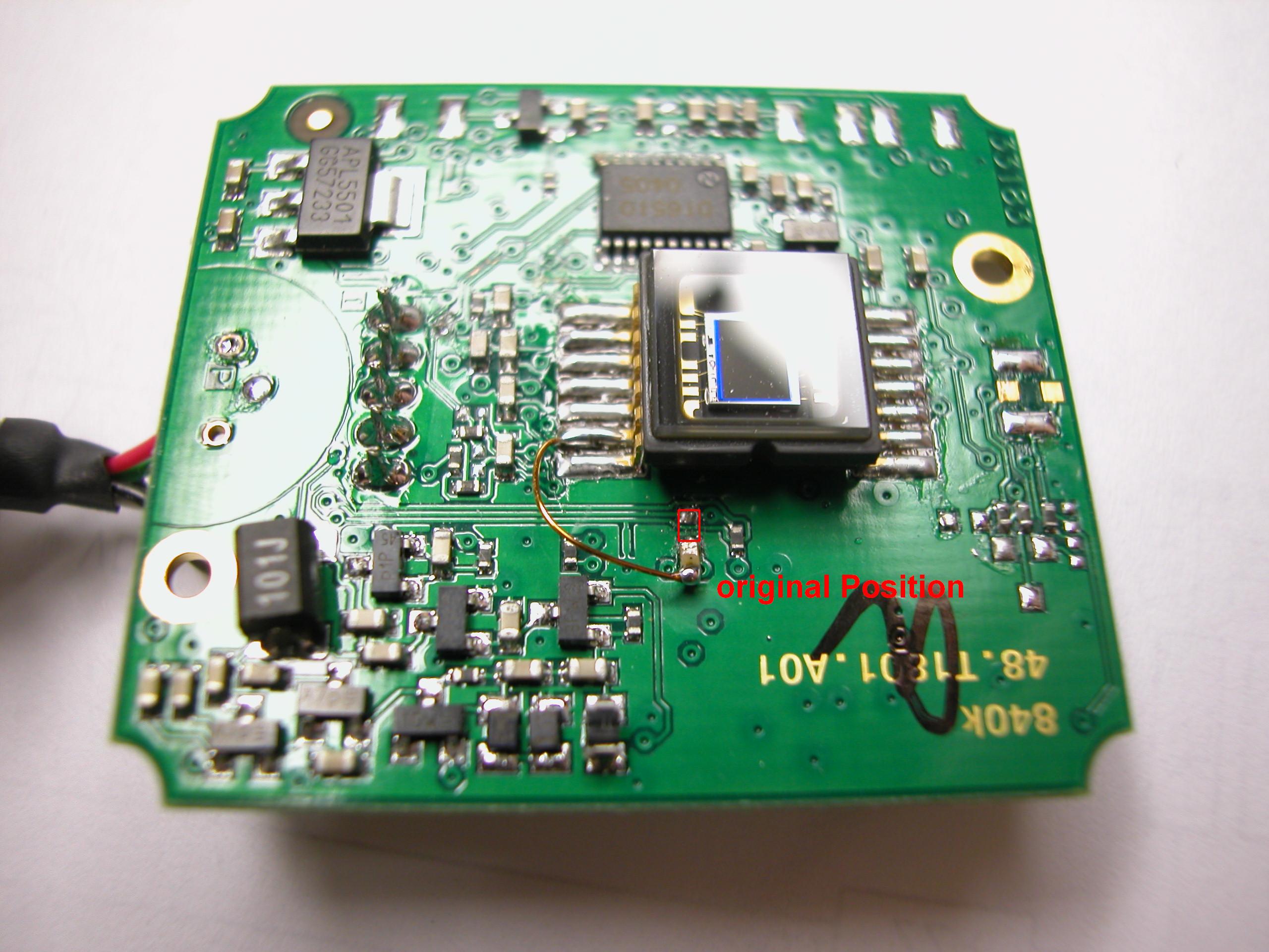
Remove the capacitor from its original position and solder it only to the pad which is further away from the CCD sensor. I'm not 100% sure if this modification is necessary. Since this is a multilayer PCB it's hard to determin what parts are connected to the CCD-side pad of this capacitor. This is only a small modification and it eliminates some risks.
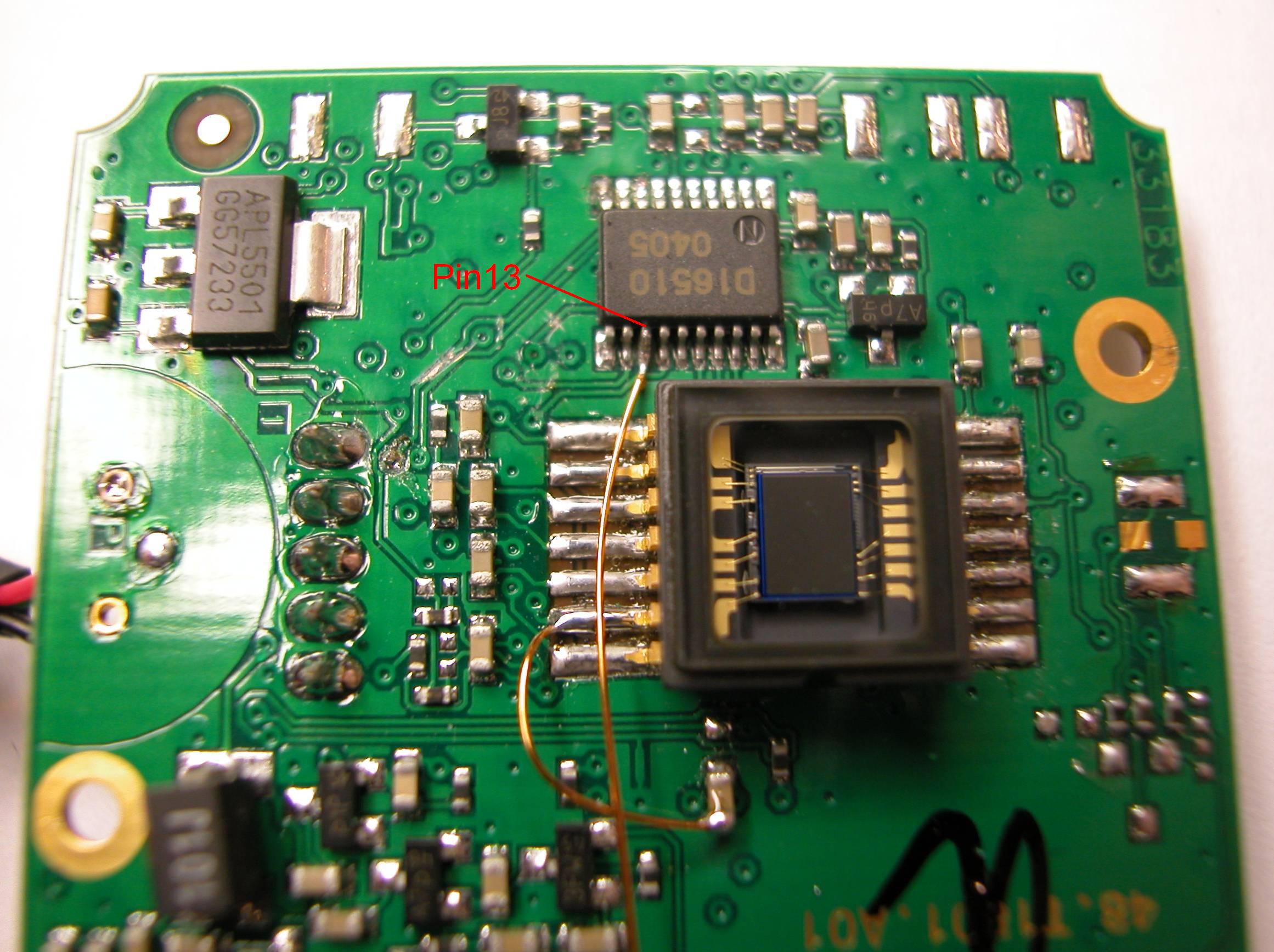
Connect the side of the capacitor which is further away from the CCD sensor (after the above described removal this side of the capacitor is floating) to pin 13 of the CCD sensor Sony ICX098BQ.
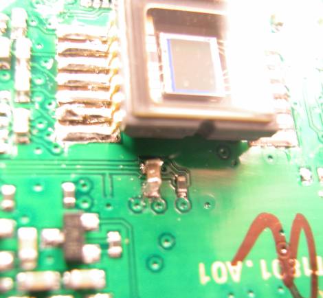
(Fig.9 move capacitor, click to enlarge)
Step6:
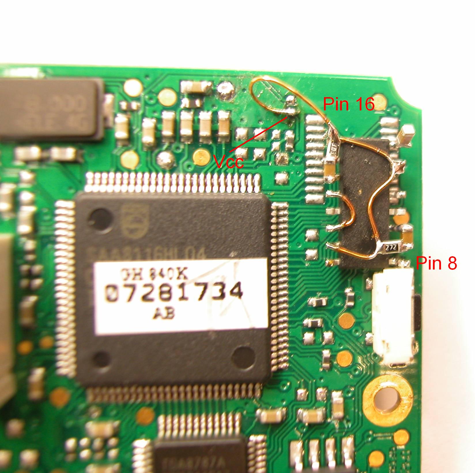
Connect Vcc (3,3V) and Gnd (0V) to the 74HC423. Use a wire to connect pin 16 to Vcc, which is present at a pad of a not soldered part. Solder pin 8 directly to the big metal part of the switch, which is connected to ground.
By connecting this pin directly to the switch, you get a pretty stable mechanical connection and don't have to glue the 74HC423 to the PCB anymore.
(Fig.10 connection to supply voltage, click to enlarge)
Step7:
Use a wire to make a connection between C1 and pin 64 RESERVED1 of the webcam processor. You don't have to solder directly to the pin, you can use the gold plated measurement point.
(Fig.11 connection to the RESERVED1 pin, click to enlarge)
#Step8:
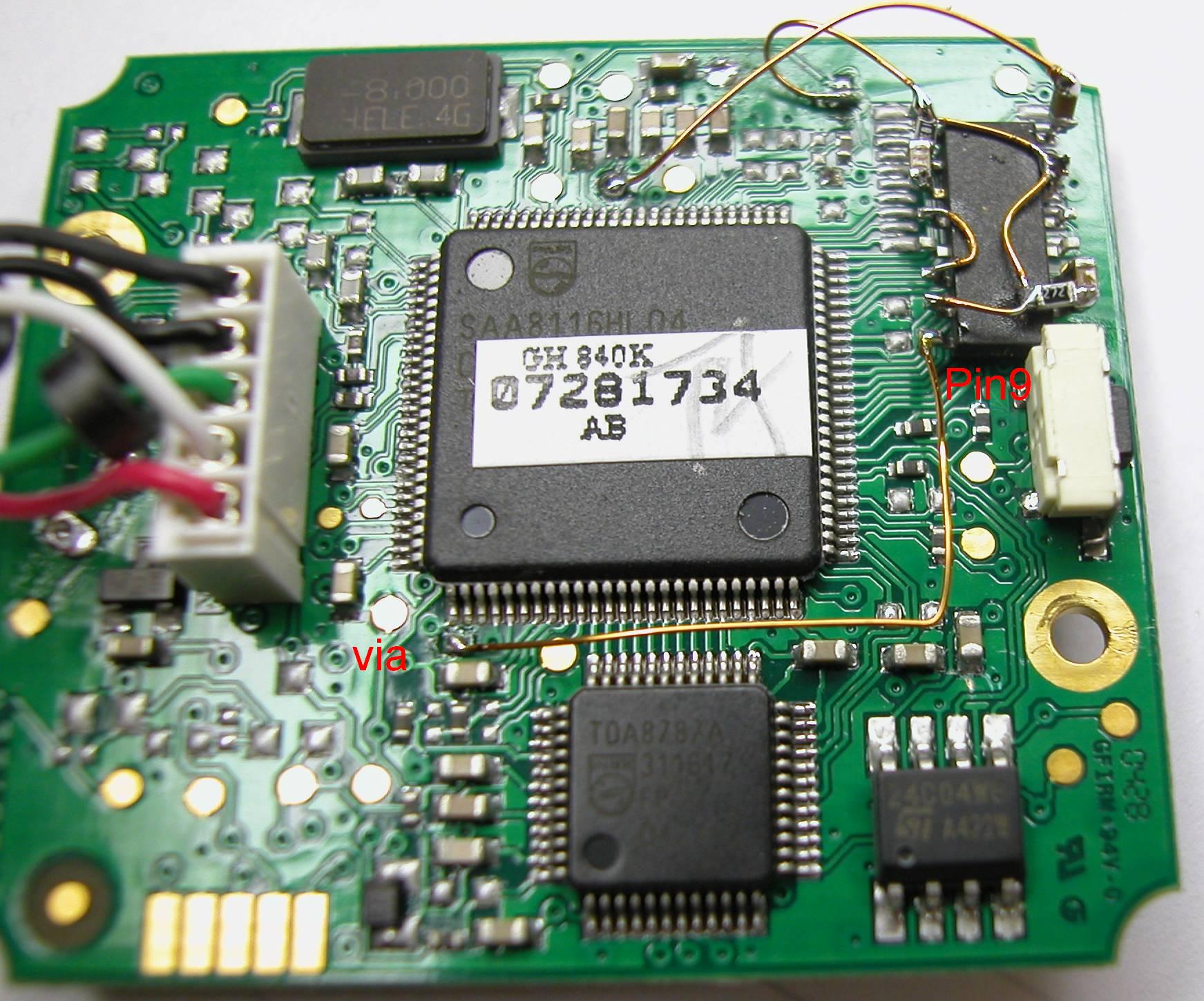
Make a connection from pin 9 of 74HC423 to pin 93 of the webcam processor. The left side of the wire is connected to a via (through connection from top to bottom layer). Use a sharp knife to scrape off the green insulating lacquer till you can see the copper and solder the wire.
(Fig.12 connection to pin 93 of webcam processor, click to enlarge)
Step9:
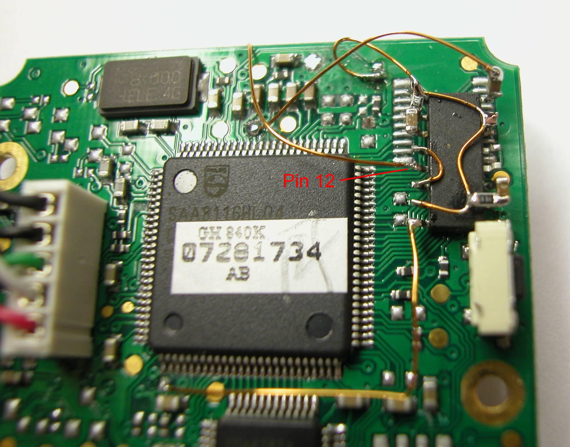
Connect pin 13 of PD16510 to pin 12 of 74HC423.
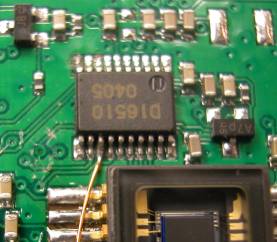
(Fig.13 connection to pin 13 of driver PD16510, click to enlarge)
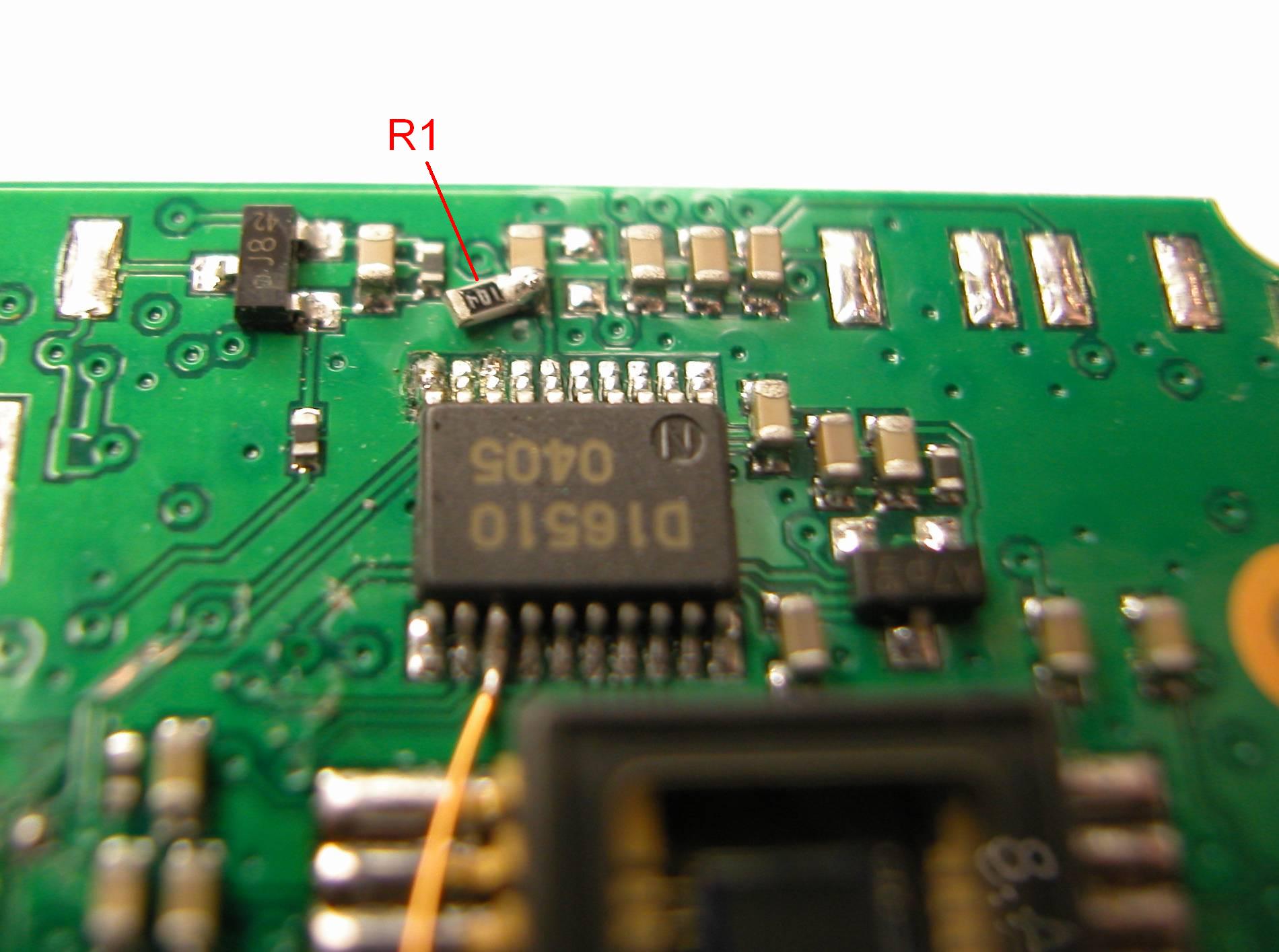
Step10:
Connect R1 to Vcc (3,3V). Make sure that the left side of R1 doesn't make any contact to other parts.
(Fig.14 Vcc connection to R1, click to enlarge)
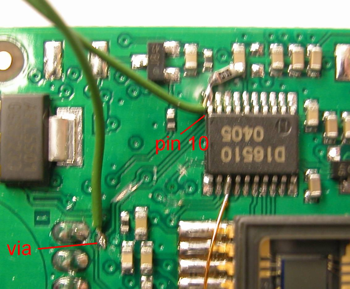
Step11:
Solder flexible wires for the switch-connection. Scrap of the green lacquer from the via to solder the left wire. Solder the right wire to pin 10 of PD16510 and R1.
(Fig.15 wires for the switch, click to enlarge)
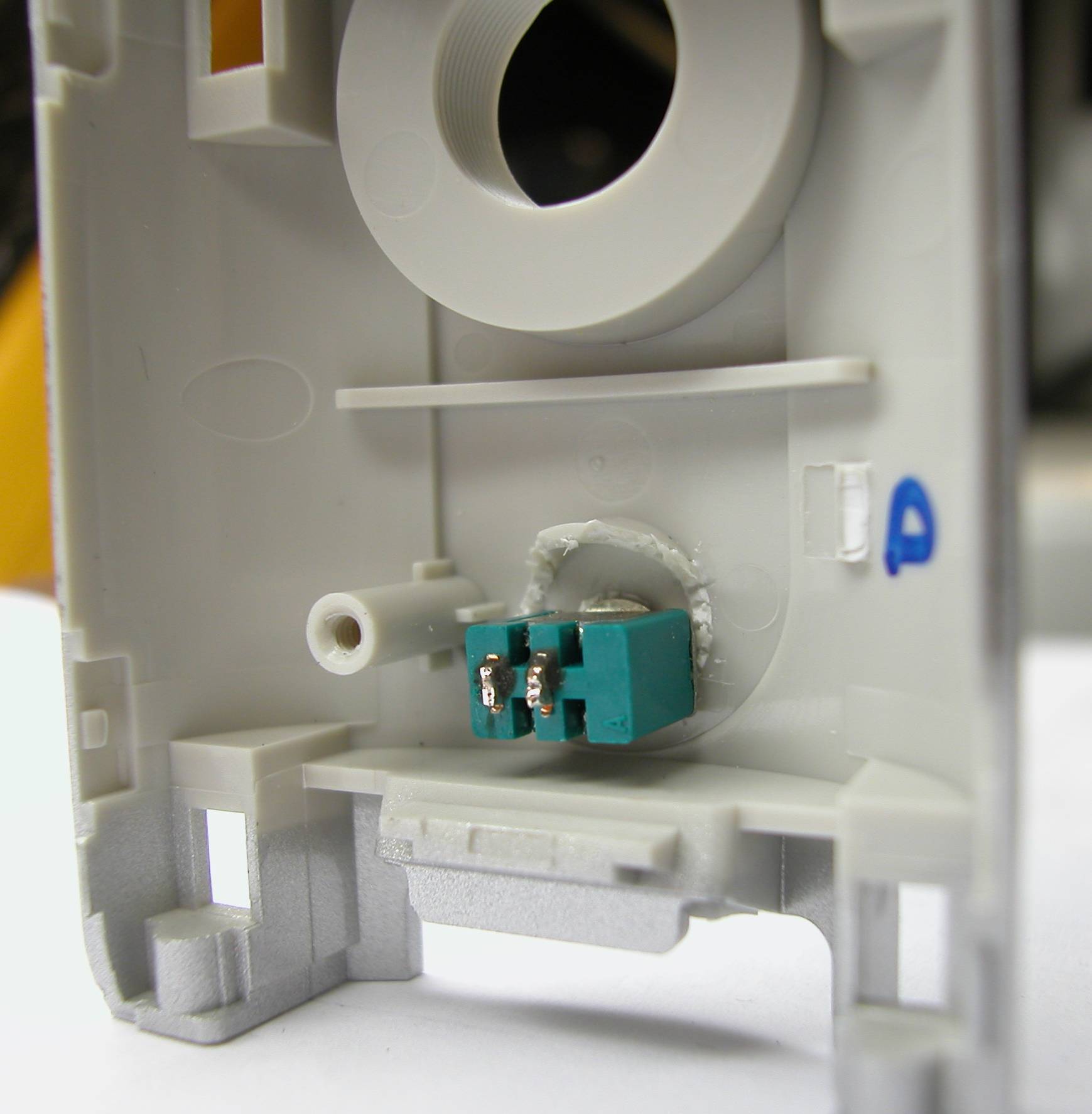
Step12:
Drill a hole through the microphone mount and place the switch. You have to remove some of the plastic around the original microphone position. I've cut away most of the contacts of the switch to avoid a short circuit with the PCB.
Once the switch is screwed to the housing you can solder the green wires from Step11 to the switch.
(Fig.16 switch, click to enlarge)
Result:
Fix the PCB again in the webcam housing with 2 screws. That's all the modification that is necessary.
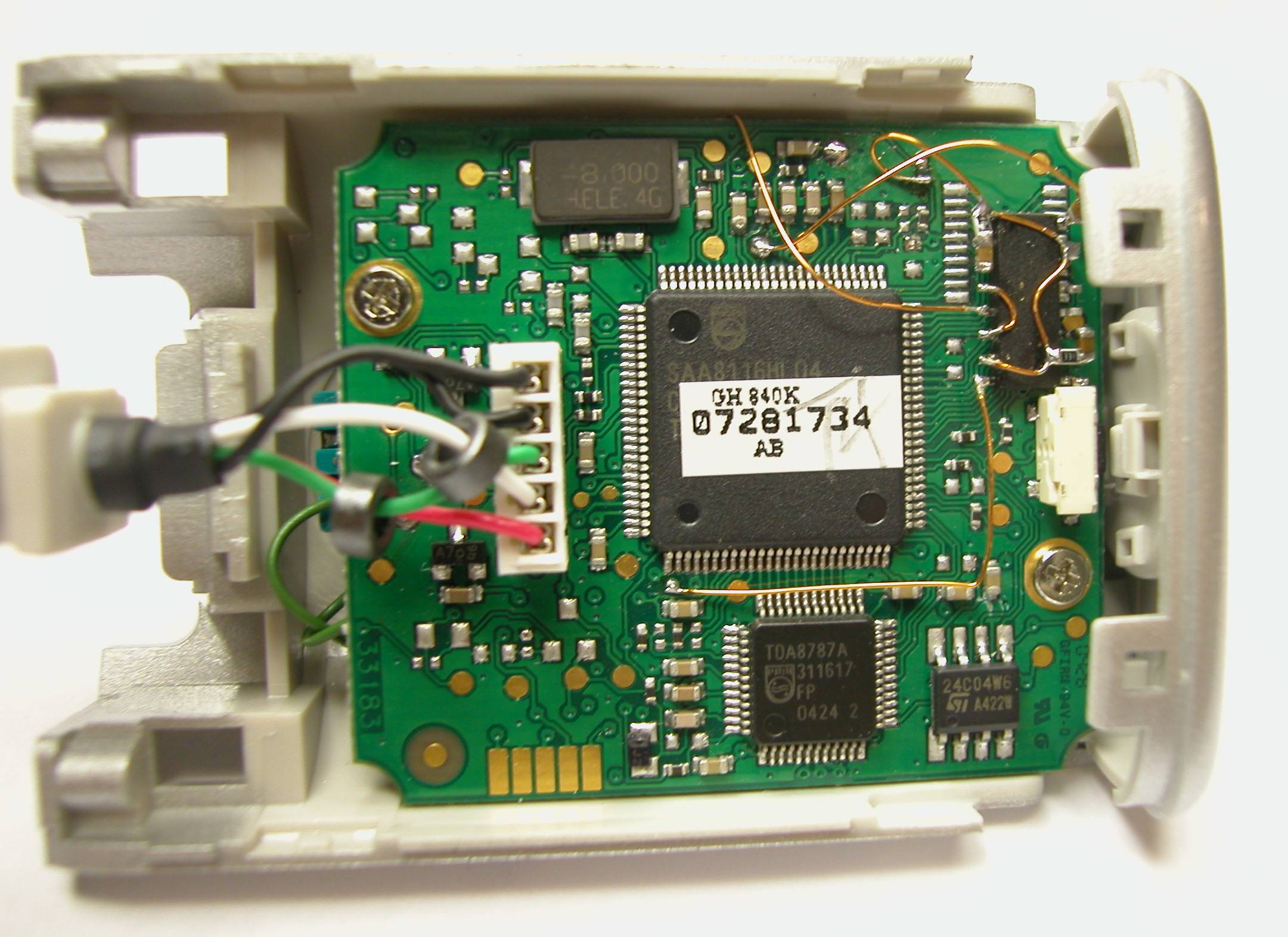
(Fig.17 back in place, click to enlarge)
If you now attach your modified webcam to the PC, you can operate your webcam like before if you move the micropohone volume slider to the top position. By moving the slider to the bottom position you block the charge transfer pulses. Unfortunately there is no software around that supports this kind of modification.
I've used Philips
VRecord to test the modification:
I moved the microphone volume slider to the top position and started a
recording. The result was a normal webcam behaviour, like there has been no
modification at all.
Then I've moved the volume slider for 10 seconds to the bottom position and
afterwards again to the top position. During this second the transfer pulses got
blocked. The frame of the movie that has been recorded after the slider has been
released again to the top position has much more brightness than the previous
frames. I used Adobe Premiere to extract frames of the avi's:
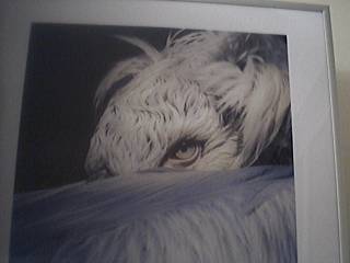
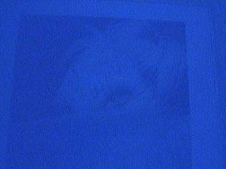
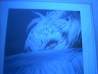
The left picture was taken at night with artifical light in the room. The middle picture was taken with no light on and gain setting near to the maximum. The right picture is the proof that my modification works: gain slider was set to minimum, recording started with VRecord, volume slider moved to min position for 10 seconds and than moved to max position again.
Pro's:
This USB only long exposure modification doesn't need additional PC-connections. Exposure time can be easily adjusted manually by simply manipulating the volume slider of the microphone interface from the webcam.
Con's:
There is currently
no software arround that supports this kind of modification. Until now all tools
are driving the parallel port to remote control the exposure time. It's not hard
to control the volume slider via software. You can download a simple application
that demonstrates how to do it. Please be aware that I'm not very familiar with
VC++. I'm a firmware and hardware guy, and have no experience in programming
VC++. If you have any remark regarding my source code I would be glad if you
could share it with me.
You are highly welcome to use my sample application. Especially if you are a
developer of one of these well known applications that remote controls the
webcam via parallel port and you want to add support for this modification!
There's another
minor drawback:
Due to the nature of the CMOS part 74HC423 this modification works only with
higher frame-rates. It won't work with frame-rates of 5,10 and 15 frames/second.
For stability reasons I would suggest to use framerates of 25 frames/second and
higher. If you feel this is a major limitation on your preferred webcam
settings, you can add an additional 100k resistor like shown in Fig.18. Adding
this resistor will enable the whole framerate range again. Step1 would be the
right time to add this resistor if you decide to do so.
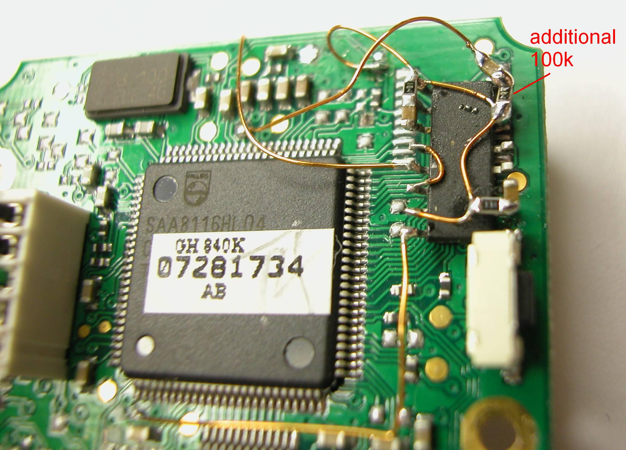
(Fig.18 additional 100k for low framerate operation)
Copyright © 2005
Michael Posavec
last update 04. feb. 2005
email: lateralusmail --> yahoo.de